Image orientation in CamiTK
CamiTK is dedicated to prototyping application in the domain of Computer Assisted Medical Intervention (CAMI), sometimes called Computer Assisted Surgery. The main target are scientists and companies that develop innovating medical devices driven by software. Clinicians can also use CamiTK in order to visualize medical data and/or to apply some image processing. It involves 2D and 3D images and interaction of these images with other components.
Images orientation has 2 purposes:
- slice visualization and
- images registration with other components.
Slice Visualization
In order to allow clinicians to go through 3D images their usual way (using Axial, Coronal and Sagittal slices), we had to find a way of orienting our images in order to visualize them.
Viewing conventions
There are two widely used viewing conventions: 1
- Radiological convention: Images are viewed as though looking upward from the feet of the subject (feet to head). “Right is Left”
- Neurological convention: Images are viewed as though looking from the top of the head downward (head to feet). “Right is right”
The DICOM standard does not feature one of this viewing convention, as the one to use. But, as many users were using the radiological convention, we decided to use this one in order to visualize all our images in CamiTK.
DICOM default orientation
DICOM defines a term, which will help choosing an orientation: “Reference Coordinates System” or RCS 2. The RCS is a very intuitive coordinate system of the patient body: X direction is from Right to Left. So if the patient is standing in front of you with the arm raised to the sides, then X direction is from the right hand to the left hand."


The patient is laying on the imager table and the clinician looks at him for it is feet.
Orientation is RAI: Right first, then Anterior first, then Inferior first. We look at the patient from his/her right (his/her right hand is the first to appear on the Axial slice), then to his/her left, then from his/her top (nose / front) to his/her back and then from his/her feet to his/her head.
CamiTK RAI convention
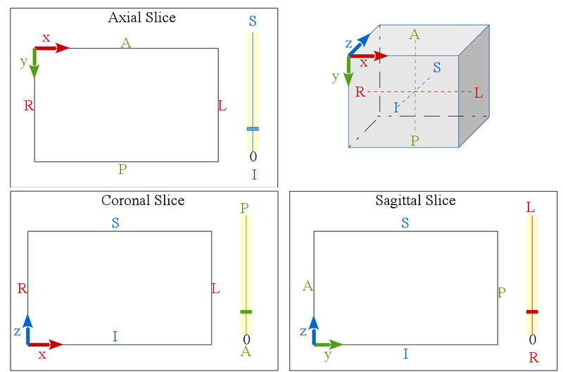
Following this DICOM RCS coordinate system, CamiTK has decided to follow the RAI orientation. This is to say, that all volume images in CamiTK (ImageComponent instances) would be oriented in order to get the image coordinate system in the RAI position, such as showed by this picture:

CamiTK slices visualization
Following this convention, now the Axial, Coronal and Sagittal viewers are tagged with patient position (Anterior / Posterior, Superior / Inferior, Right / Left) in order to locate more easily each slice of the image.
 |
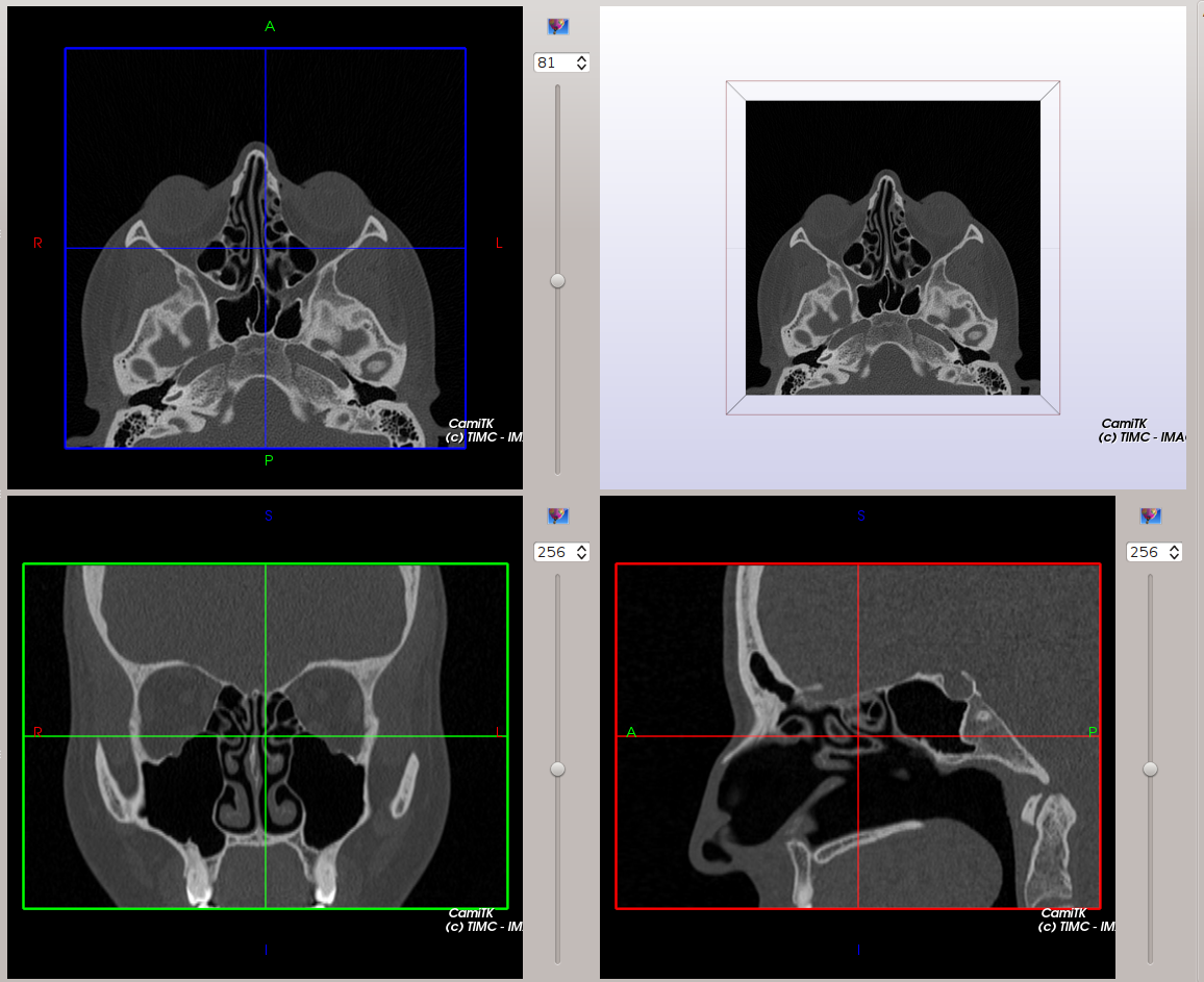 |
Our MedicalImageViewer is inspired from Slicer3.
CamiTK DICOM visualization
DICOM are specific volumic images, read from a directory containing several files of a serie, belonging to a study. In order to correclty orient the image, the following DICOM tags are taken into account:
- (0020, 0037) Image Orientation Patient: also called “Direct cos angles” this information allow us to deduce the rotation from the image coordinate system (what was the orientation of the patient when the image was acquired) to the RAI coordinate system.
- (0020, 0032) Image Position Patient: gives the position of the first voxel of the image. Allow to deduce the translation from the scanner coordinate system to the patient coordinate system (RAI). By default, the scanner coordinate system is the world coordinate system in the 3D viewer.
Technical implementation
This section deals on how we implemented this feature into CamiTK. It is intended mainly for developers or curious people. All the implementation is done in the camitk::ImageComponent class using the camitk::ImageOrientationHelper class.
You may find a lot of information on these class taking a look at the API documentation.
ImageOrientationHelper
This class allows one to simply compute the 3D transformation matrix FROM and TO any direct orientation possible TO and FROM the RAI coordinate system. This class is really helpful when dealing with orientation. You may use it to perform any manual orientation, if, for instance your component fails to read the orientation information from your file.
Note that this class is also used by the ReorientImage class, which allows to visualize any of direct orientation coordinate systems in a 3D view and apply the 3D transformation to the RAI coordinate system in order to reorient the image. This action could be minimally use to visualize the different possible orientation as it features a 3D viewer (displayed in the action viewer).
ImageComponent
The ImageComponent class is the main CamiTK component class dealing with volume images. The ImageComponent::setImageData(...) method allows one to set the vtkImageData pointer to the volume image data. This method takes one initial orientation as an input. This orientation is one of the 22 direct possible orientations described in the ImageOrientationHelper class and it is the one your component has been able to compute thanks to its file header information. By default, if no orientation is provided, the setImageData method consider your input vtkImageData as already oriented in the RAI coordinate system: no reorientation is done then.
Given an input vtkImageData pointer to your image data and a orientation, the setImageData(...) method will perform the following steps:
- Compute the translation from the 1st voxel of the image to the origin (0, 0, 0)
- For instance with DICOM image files, this information is provided by the Image Position Patient tag.
- Compute the 3D transformation to reorient your image from its initial orientation to the RAI coordinate system.
- With DICOM, this information is provided by the Image Orientation Patient tag.
- Compute the global 3D transformation T = translation + orientation.
- Apply it to the image data
- Store the inverse 3D transformation T-1 as the component’s frame. If the component already has a non null frame, we multiply it with this transformation. This last step is really important and allows to:
- Still represent volume images in the 3D viewer as they were acquired, i.e., considering their translation from the origin and their acquired orientation.
- Correctly visualize Axial, Coronal and Sagittal slices in the respective slice viewers. Those viewers can only display good slice information if the image is translated to the origin (0, 0, 0) and correctly orientated in the RAI coordinate system.
InteractiveViewer
The slice that is shown in the 2D interactive viewers (axial, coronal and sagittal planes for instances) is a view from a camera situated in the world reference frame. The slice number shift is applied to the camera as well. As a animation is always clearer, here is one:

In this animation, 3 things are represented:
- the image. The image has a specific frame, different from the world reference frame. The image is displayed in 3D at its specific frame and is represented here as the cube with red edges on the bottom left. The three orientation slices are displayed as well in 3D. Note that there is a non null translation and non Id rotation in this frame.
- The world reference frame. It is shown on the top right corner.
- The axial camera visible bounding box. The thin slice edges that are seen beside the world reference frame is the what the axial viewer camera is displaying.
During the animation, the camera visible bounds are shifted as the axial slice number increases.
Save the image
VTK does not support frame. If you try to save both your image and its frame using the header of MHA file, there will be some errors on the data. To avoid this problem, we choose to save only the basic VTK image, without its frame transform. You can save your transform using the action edit frame action in the section save/load transform.
References
Feedback
Was this page helpful?
Glad to hear it! Please tell us how we can improve.
Sorry to hear that. Please tell us how we can improve.