Frames and geometrical Transformations in CamiTK
New in CamiTK 6.0, the previous Frame system was totally rethought and replaced by the one described in this page. Please check migration guide if you need to port older code to the new system.
Main classes in the C++ API doc: TransformationManager, FrameOfReference, Transformation.
Main classes in Python API doc: TransformationManager, Transformation.
Overview
In CamiTK, most Components are used to store data located in 3D space, such as meshes (3D points and polygons) and 3D images (voxels). All the data of a Component are located in 3D space relatively to a frame of reference. A frame of reference defines an origin and 3 axes, represented by the FrameOfReference class.
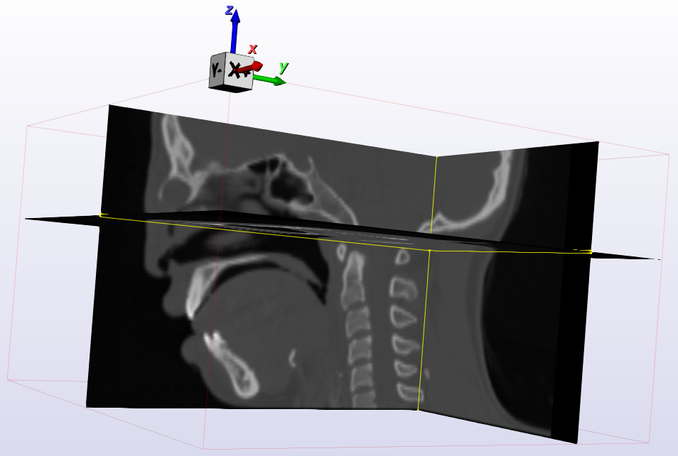
For instance here is a CT image and its frame (origin and axes):
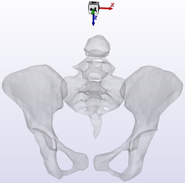
And here is a mesh and its frame (origin and axes)
Components can use a specific frame (data from one component are not defined in the same frame than data from another component) or share the same frame (all their data are relative to the same frame).
In order to visualize or process data from multiple components, the relationship between those frames must be known.
To transform data from a frame to another, CamiTK provides a Transformation. It supports linear transformations.
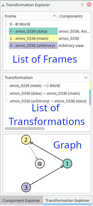
The Frames and Transformations form a graph which is managed by the TransformationManager class, and displayed by the Transformation Explorer viewer:
Users can interactively or programmatically:
- set/modify the Frame of a Component
- define anatomical labels to their axes
They can manipulate the frame relationships (transformation graph) by interactively or programmatically:
- add a Transformation between two existing frames
- remove a Transformation between two existing frames,
- edit the Transformations between Frames (edit the 4x4 matrix values)
The TransformationManager can compute Transformations that link a Frame to any other Frame by finding a path of Transformations between those Frames, so the user can always transform the coordinates from a Component to another Component’s Frame.
If no Transformation was specified, CamiTK adds a default identity Transformation between the Commponent’s Frame and a “World Frame” which represents a common space used by CamiTK to ensure it is always possible to display two Components in a common Frame.
Example
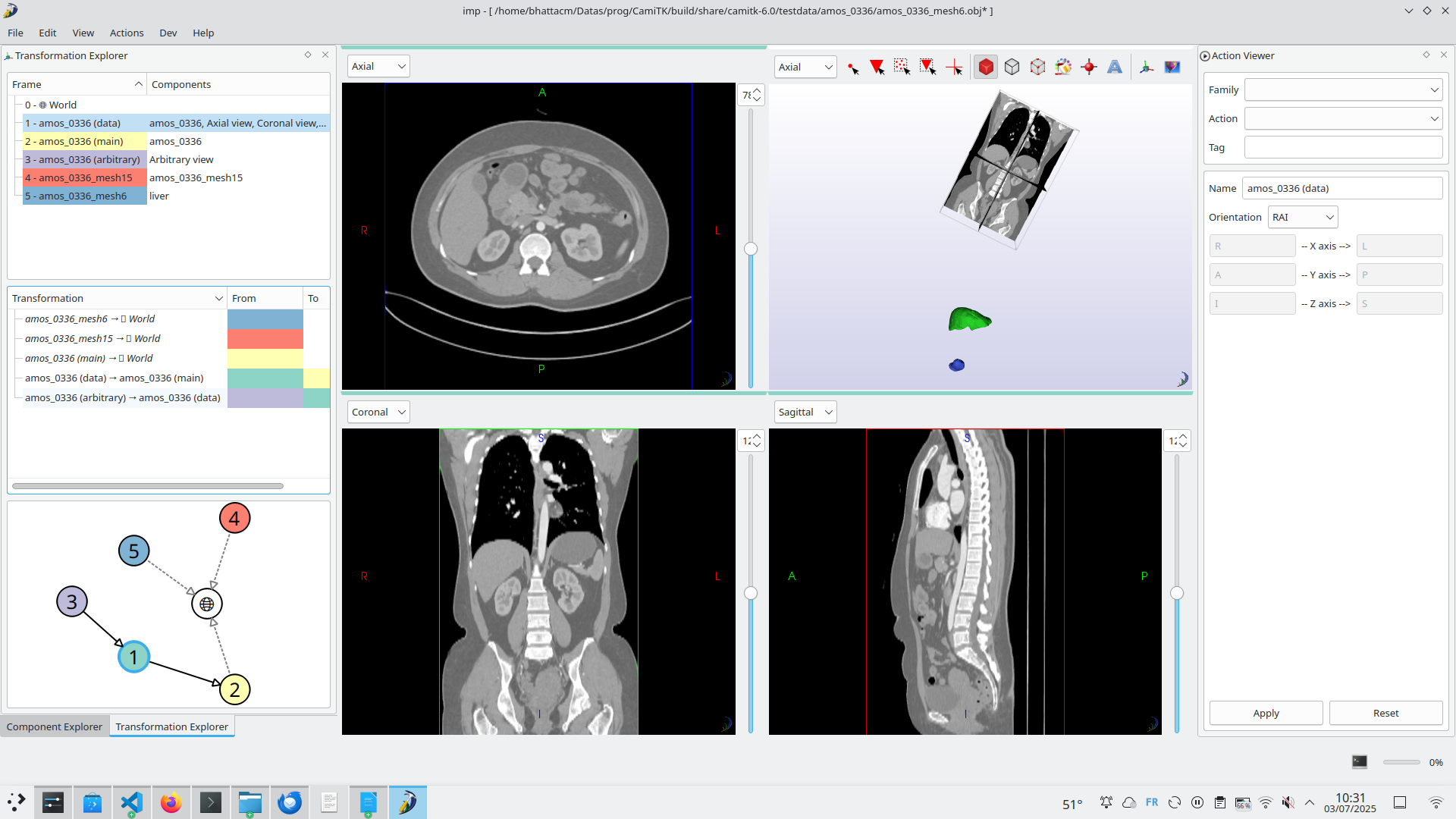
Load a CT scan and two meshes computed from the CT scan.
-
First, the CT scan is opened. CamiTK reads the Image and creates two Frames, the Data Frame 1 (in which the raw voxel data is stored), and the Main Frame 2 which is the Frame that the CT scanner attributed to the image. It usually refers to the CT machine itself. A Transformation 1→2 between those two Frames is provided in the file, and loaded by CamiTK (black arrow in the graph).
-
We edit the Data Frame of the image (Action on the right side) to set the anatomical orientation of the image to RAI (see below for more detail) so that the 2D views display the correct labels.
-
We open two meshes. Each mesh is loaded and CamiTK creates a new Frame for each mesh, Frame 4 and Frame 5.
-
By default, CamiTK does not know how those three objects relate to one another, because no Transformation was provided between their Frames. It creates a default Transformation between the main Frame of the image and its World Frame, and does the same for both meshes (three default transformations - identity - displayed as dashed arrows in the graph)
-
We want to provide the correct information about the relationship between the meshes’ frames and the image’s Frames.
-
In this example, both meshes were computed from the Image, and their vertices coordinates are expressed in the image’s Data Frame.
-
We have two possible ways to do this:
- Set the Frame of each mesh to Frame 1 using the Set Frame From Action
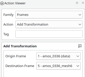
- Add a Transformation linking the mesh Frame 5 with the image data Frame 1 using Add Transformation Action. By default, CamiTK adds an identity Transformation
After adding the Transformation:
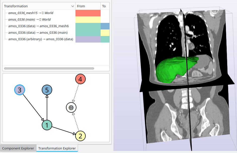
- We can see that the default Transformation linking the mesh Frame 5 to the World Frame was removed and replaced by the Transformation 1→5 to the image Data Frame 1.
- The mesh is now aligned with the image
- You can now save the workspace, and CamiTK will remember the Frames and Transformations between them for the complete scene.
FrameOfReference
A Frame of reference is an object that represents a system of coordinates in 3D space: an origin and 3 axes. It does not contains any data by itself, only a unique identifier (UUID), name and description. Its UUID allows to save and load Frames and Components and ensure that their respective spaces can be restored
AnatomicalOrientation
A Frame may additionally contain anatomical labels associated to its axes (e.g. Right, Left, Apex…), so that CamiTK knows the label to display in 2D Views, using the AnatomicalOrientation class. If an image is stored using RAI orientation, only the labels of its Frames indicate this. CamiTK can thus support any orientation of the data, and the Viewer class is responsible to display it in the required orientation according to the AnatomicalOrientation labels. The standard 3-letter orientation are supported, using the following convention: Letters can be R (right), L (left), A (anterior), P (posterior), I (inferior) or F (foot), S (superior) or H (head). “RAI” means that the first axis goes from Right to Left, the second from Anterior to Posterior, and the third from Inferior to Superior. The “+” variant reverses this convention, so “LPS+” is equivalent to “RAI”.
If you need to use non-standard labels (e.g. “Base” and “Apex” for the heart), this is supported using custom labels. You can use Action EditAnatomicalInformation, or in your own code, AnatomicalOrientation’s API.
CamiTK used to load all images as RAI, this is no longer the case. CamiTK will try to fill AnatomicalInformation according to the header data of the file formats it supports, but this data is usually not reliable, and each piece of software may use its own convention when writing file. This is why you should always check that the data you import has the right information. If the information is incorrect, you should edit the Frame’s Anatomical Orientation, and save your Workspace in the .camitk file format, which will ensure this information is saved correctly.
Transformation
CamiTK supports 3D linear Transformations, represented by a 4x4 matrix. Each Transformation links a Frame (from) to another Frame(to). It has a unique identifier (UUID), a name, a description, and a matrix.
The 4x4 Matrix is stored in a vtkTransform 1 0 0 Tx 0 2 0 Ty 0 0 3 Tz 0 0 0 1
In this example, (Tx, Ty, Tz) is a translation (possible due to the use of homogeneous coordinates), and the transformation scales X dimension by 1, Y axis by 2, Z axis by 3. There is no rotation of the axes here.
A 3D Point is encoded in homogeneous coordinates: x y z 1
In that way, multiplying the point vector by the matrix will transform it into the “to” Frame. For this, you can use Transformation::getTransform()to get the internal vtkTransform.
Component’s InterfaceFrame
Each Component has a FrameOfReference used to define how it is spatially related to other Components.
To access it, Component has an interface called InterfaceFrame, that allows to manipulate its FrameOfReference using getFrame(), setFrame(), and setFrameFrom() to just copy the Frame from another Component.
Some Components may manage additional Frames and Transformations (e.g. Images) using other methods.
See InterfaceFrame reference documentation for more information.
ImageComponent: Data FrameOfReference
In the case of ImageComponent, there are two main Frames: the Data Frame that has its origin at the center of the first voxel, and which axes match the direction of the voxel matrix, and the Frame which is used as a reference for the image. Usually, this Frame comes from the acquisition method (e.g. scanner-based frame) or is linked to the position of the patient. For example, when two MRI sequences are acquired in the same sessions, they usually have the same main Frame, even if the Data Frame is different (e.g. different angle of field-of-view).
You can use get/setDataFrame()to manipulate the Data Frame of ImageComponents.
The Transformation between the Data Frame and the main Frame is also stored in the ImageComponent and can be accessed using getMainTransformation().
As some images have additional Frames (registration to a standard template) and Transformation, you can access those using InterfaceFrame other methods.
TransformationManager
Ownership
In C++, object ownership must be managed carrefully to avoid memory issues. As a Frame can be used by multiple components, we used std::shared_ptr to manage ownership.
The TransformationManager is a static class that owns all Frames and Transformation objects. To create a Frame or a Transformation, you must use TransformationManager’s methods.
If you use TransformationManager::getTransformation, which returns a raw Transformation* pointer, keep in mind that you must use it immediately and not store it, as it may be deleted if considered unused by the TransformationManager later. If you need to get ownership of a Frame or Transformation (e.g. to store it in your Component), use getFrameOfReferenceOwnership() and getTransformationOwnership()to get a std::shared_ptr that you can store. TransformationManaget will never delete a Frame or a Transformation that still have a shared_ptr pointing to it.
API
TransformationManager allows you to create, modify and remove Frames and Transformations, and maintains a graph of Transformations between Frames which must be acyclic: there cannot be multiple paths linking two Frames. This is the main reason why adding a Transformation may fail. In that case you may either delete a Transformation before adding your own using removeTransformation, or update an existing one using updateTransformation().
For more details, see TransformationManager’s API documentation.
WorldFrame
In order to display multiple Components in the same Viewer, CamiTK needs to know how the Frames of all Components are linked to each other: CamiTK needs a common Frame of Reference, called the WorldFrame. Each Viewer uses a Frame, so if a Component is displayed in a Viewer, TransformationManager must provide a Transformation from the Component’s Frame to the Viewer’s Frame. If no Transformation was provided, CamiTK adds an Identity Transformation (called a defaultIdentityTransform) linking the Component’s Frame to CamiTK’s internal World Frame. This ensures that the Component can be displayed in the Viewer. Obviously, this may display a Component in the wrong place in relation to another, but this means that the user should add a Transformation between the Frames of the relevant Components
Transformation Explorer
TransformationExplorer is a Viewer that shows the list of Frames, the list of Transformations, and the Transformation graph. It available in IMP on the left panel in its own tab. Right-clicking on Frames or Transformations allows edit, add or remove actions.
Usage in CEP extensions development
Components
By default, a Component creates a new Frame in its constructor and does not store a Transformation. If you need to store more Frames and/or Transformations, you have to add std:shared<FrameOfReference> and std::shared<Transformation> pointers in your class members and reimplement InterfaceFrame methods. See ImageComponent for an example of this use. You can then use TransformationManager API to add Frames and Transformations.
Actions
Actions that create or modify data may need to manage Frames and Transformations.
- Simplest case: thresholding an ImageComponent creates a new ImageComponent which uses the same Frames as the original one. In that case, you can use òutputImage->setFrameFrom(inputImage)
- More complex case: you extract an ROI from an ImageComponent. In that case, you want your new Image to be correctly aligned with the same Frame as the original ImageComponent. So you need to compute the combination of the ROI translation followed by the MainTransformation of the original ImageComponent. You new image will use its own Data Frame, its own MainTransformation linking its Data Frame to the common main Frame. You will use
ImageComponent::setFramesAndTransformationto set the Frames and Transformation at the same time.
Supplementary information about Anatomical orientation
Each Frame has an AnatomicalOrientation object that assigns, if known, each axis to an anatomical direction. For example, the first axis X might be going from the left to the right of the patient, the second axis Y might correspond to the ventral-dorsal direction, and Z to the inferior to superior direction. Custom anatomical direction may be defined (e.g. organ-specific axes). This information is used mostly for display in viewers.
AnatomicalOrientation should be set by the components I/O (e.g. using DICOM fields when reading a DICOM), by Actions creating a component, or by the user.
Orientation Conventions
-
For volume images, axes can be stored in an arbitrary order depending on the file format, header, and software used to create the file.
-
Images can be stored on disk using one convention, with a header information indicating which anatomical direction might correspond to the image acquisition planes. For example in DICOM, the position of the patient in the machine (e.g. upright, lying on their back…) must be taken into account and a geometrical transformation provides the position and orientation of the image in relation with the machine.
-
3-letter notation: anatomical orientation is often specified as a three letter code, with letters L (left), R (right), I(inferior), S (superior), A (anterior), P (posterior). Each letter indicates for each axis where it originates. For example, RAI means axes go from the right to the left of the patient (X axis), from the anterior to the posterior side (Y axis), and from the inferior to the superior side (Z axis).
-
Unfortunately an opposite notation is sometimes used, in which the letter represents the direction towards which the axis is oriented. It can be specified with a plus sign. For example RAI+ means the axes go from left to right, from posterior to anterior, from superior to anterior. This is the notation used (without the +) by 3D Slicer on its website and by the NRRD format specification.
-
DICOM may specify anatomical orientation in header (0020,0020). It uses a + notation and calls Head-Foot the Inferior-Superior axis, and can specify anatomical direction for quadruped animals as well. If this header is not defined, a combination of Image Orientation (Patient) (0020,0037) and Image Position (Patient) (0020,0032) should be present.
To understand those, DICOM defines a Reference Coordinate System (RCS) which corresponds to RAI orientation.
(0020,0037) contains 6 value, the first 3 are the coordinates of a vector corresponding to the X axis of the RCS (right to left of the patient), and the next 3 the coordinates of a vector corresponding to the Y axis of the RCS.
-
In the real world, header data might be wrong (e.g. patient was installed in a different position, and the technician did not update the setting on the scanner). This is why there is an action to manually set AnatomicalOrientation as needed.
-
Voxel coordinates to Data Frame coordinates: the center of the first voxel (0,0,0) has data coordinates (0.0, 0.0, 0.0). This means that parts of voxels may have negative coordinates as the (0.0, 0.0, 0.0) point is not the corner of the first voxel, but its center.
-
CamiTK used to have a default orientation, meaning that images would be flipped on load to be stored in the RAI convention. CamiTK is now neutral about how images are stored in memory or on file, but AnatomicalOrientation can be used by viewers to choose how to display them.